Contents
- Part I - The Decision to Operate
- Part II - The AO Principles and the Central Dichotomy
- Part III - Implants and Biomaterials
- Part IV - Screws and the Lag Principle
- Part V - Plates and Their Functions
- Part VI - The Tension Band Principle
- Part VII - Intramedullary Nailing
- Part VIII - External Fixation
- Part IX - Biomechanics of Fixation: A Summary
- Part X - Removal of Osteosynthesis Hardware
- References
Part I - The Decision to Operate
Non-operative treatment remains the commonest way to manage a fracture, so the first question is never “how shall I fix this?” but “does this fracture need fixing at all?” Surgery earns its place when a fracture cannot achieve or hold an acceptable position in a cast, when the joint surface must be reconstructed, or when the biology and the patient demand early mobility that immobilisation cannot deliver.
The accepted operative indications are an unacceptable or unmaintainable closed reduction (the unstable diaphyseal fracture, the displaced wrist that re-displaces), a displaced intra-articular fracture needing anatomical restoration of the joint surface, the displaced femoral and tibial shaft (where intramedullary nailing is decisively better than traction or cast), the both-bone forearm in an adult (a functional two-bone “joint” that demands restored length and rotation), open fractures (which need debridement and stabilisation together), fractures with neurovascular injury or compartment syndrome, pathological fractures, and the polytrauma patient in whom skeletal stabilisation is part of resuscitation.[1] The recommended order for nailing closed fractures in a multiply injured patient is instructive: femur, then tibia, then pelvis or spine, then upper limb.[2]
Timing matters as much as the decision itself. In the multiply injured patient the modern doctrine is damage-control orthopaedics (DCO): rather than definitive fixation of every fracture at once (“early total care”), the unstable patient receives rapid, minimally invasive temporary stabilisation, usually a spanning external fixator, with definitive surgery deferred until physiology has recovered.[3] The principle is the “two-hit” model: the injury is the first hit, and an ill-timed major operation is a damaging second hit. Patients are categorised as stable, borderline, unstable or in extremis, and the in-extremis patient receives damage-control surgery, with definitive fixation typically at 5-7 days.[4] Vallier and colleagues, reviewing 1,442 patients, found chest injury the single greatest predictor of pulmonary complications, and recommended early definitive fixation within about 36 hours in patients who respond to resuscitation, guided by markers of adequate resuscitation (lactate < 4.0 mmol/L, pH > 7.25, an acceptable base deficit).[5]
Part II - The AO Principles and the Central Dichotomy
The four AO principles
The Arbeitsgemeinschaft für Osteosynthesefragen (AO/ASIF), founded in 1958, codified the principles that still govern operative fracture care. Stated in their classic form, they are:[6]
- Anatomical reduction of the fracture fragments, especially of an articular surface, to restore the bony architecture.
- Stable fixation appropriate to the “personality” of the fracture: absolute stability where it is needed, relative stability where it is better.
- Preservation of the blood supply to bone and soft tissue by atraumatic, “biological” surgical technique.
- Early, active, pain-free mobilisation of the limb and the patient, which prevents the stiffness, wasting and osteopenia of “fracture disease.”
The history of the field is the story of the balance between the first principle and the third. Early AO surgery pursued rigid anatomical fixation of every fragment; experience showed that the dissection required to achieve it could devitalise the very bone it reconstructed. The pendulum swung toward biological fixation (relative stability, indirect reduction, callus healing) for comminuted and diaphyseal fractures, while absolute stability was reserved for articular and simple fractures.[7] Rockwood is candid that the optimum is still not settled: “the optimal stability for a given fracture has not yet been determined.”[8]
Absolute versus relative stability
This is the single most important concept in operative fracture treatment, because it determines both the implant chosen and the way the bone will heal.
Absolute stability is achieved by anatomical reduction plus interfragmentary compression (a lag screw, a compression plate, a buttress plate). It reduces motion at the fracture to nearly zero, and the bone heals by primary (direct) healing, without callus, through Haversian (osteonal) remodelling across the fracture.[9] The AO text gives a memorable corollary: “Callus formation after attempts at fixation with absolute stability indicates a degree of instability that ultimately may lead to implant fatigue and failure.”[10] Direct healing is also slower than callus healing.[11]
Relative stability is fixation that permits some controlled motion (a bridge plate, an intramedullary nail, an external fixator). It heals by secondary (indirect) healing, with callus, through endochondral and intramembranous ossification.[12] This is the mode for multifragmentary and diaphyseal fractures.
Perren’s interfragmentary strain theory
Why does the same construct that is ideal for a comminuted fracture cause a simple fracture to fail? The answer is strain. Strain is a dimensionless quantity: the change in the fracture gap divided by the original gap width, or in clinical terms the amount of motion at a fracture divided by the fracture surface area.[13] Healing tissues each tolerate a characteristic strain: granulation/fibrous tissue tolerates about 100% strain, cartilage about 15%, and bone only about 2%.[14] A tissue forms only when the local strain falls below its tolerance, and each tissue forms under the protection of its stiffer predecessor.
The geometry follows directly. A simple fracture has a small gap and a small surface area, so a given amount of motion produces high strain: fibrous tissue or nonunion. The same motion at a comminuted fracture is shared across many surfaces, so the strain at each is low, and callus forms.[15] Perren’s worked example makes it concrete: in a 10-micrometre gap a single cell ruptures with minimal distraction (high strain), whereas in a 20-micrometre gap with room for several cell layers the same distraction merely stretches them (low strain).[16] This is why a bridging construct must never be used on a simple fracture: too few surfaces to share the motion, strain too high, and the plate eventually fatigues and breaks.[17] Strain is also dynamic and self-correcting: as granulation tissue forms and resorption widens the gap, strain falls and the tissue sequence (fibrous → cartilage → bone) can proceed.[18] Importantly, zero strain is not the goal: some load and motion are needed to stimulate callus in a relative-stability environment.[19]
Part III - Implants and Biomaterials
Metal has dominated fracture fixation for decades because it combines high stiffness and strength with good ductility, biocompatibility and reliable function.[20] Three materials matter clinically: electropolished stainless steel (316L), commercially pure titanium (cpTi), and titanium alloys such as Ti-6Al-7Nb (TAN) or Ti-6Al-4V.[21]
The decisive property is the modulus of elasticity (stiffness). Stainless steel sits at about 186-200 GPa, titanium at about 100-110 GPa, and cortical bone at only about 15-20 GPa.[22] Steel is therefore roughly thirteen times stiffer than bone; titanium is about half as stiff as steel and so closer to bone. A more flexible titanium implant deforms more like the bone it splints, which gives it superior fatigue resistance under cyclic load, a real advantage where micromotion is expected, and some clinical series suggest better healing of fractures bridged with titanium than with steel locking plates.[23] Steel, being more ductile, is easier to contour; titanium gives less tactile feedback during insertion and is harder to bend.[24]
The old belief that a stiff plate weakens the bone beneath it by stress shielding has been substantially overturned. The AO text attributes the temporary porosis seen under a plate not to unloading but to necrosis-driven internal remodelling from disturbed cortical blood flow: the porosis is transient, its pattern matches the disturbed circulation rather than the unloaded zone, and plastic plates can produce more porosis than steel ones.[25] The practical lesson is to minimise periosteal stripping and avoid pressing the plate hard onto the bone, the rationale for the limited-contact and locking plates discussed below.
Biocompatibility differences are clinically relevant. Titanium forms a stable, self-renewing oxide passivation layer and is almost inert; stainless steel is susceptible to crevice and fretting corrosion.[26] Implant-quality stainless steel contains 13-16% nickel, and clinically relevant nickel allergy occurs in 1-2% of internal-fixation patients, so titanium is preferred in known nickel allergy.[27] For MRI, titanium implants are non-magnetic and produce few artefacts, while 316L steel is paramagnetic; both are safe to scan, with artefact size proportional to implant mass.[28] Where flexible fixation and fretting are expected, titanium is the material of choice; smooth, polished surfaces ease later removal and discourage tissue and bacterial adhesion.[29]
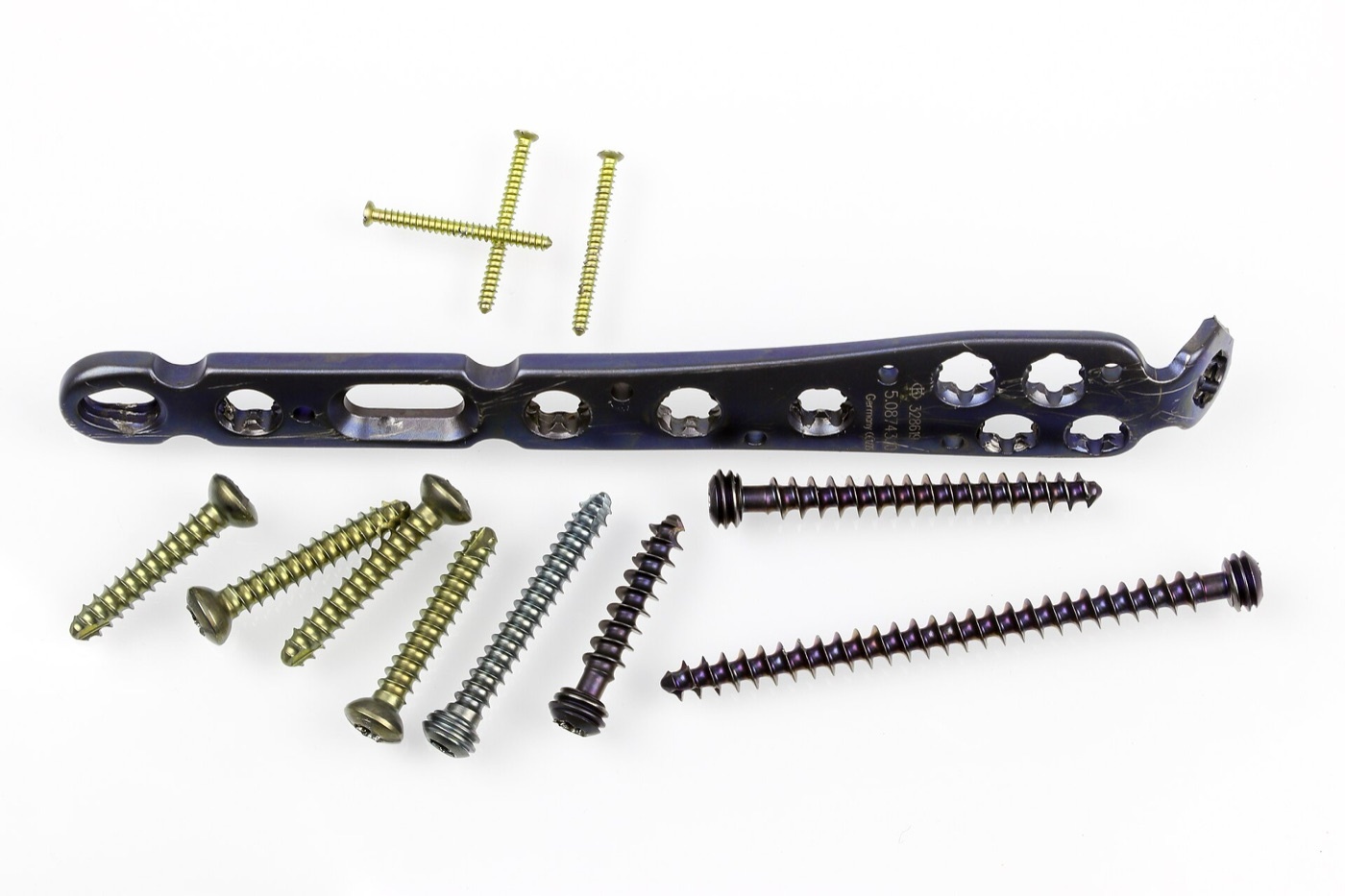
Figure 1. An assortment of osteosynthesis hardware: an angular-stable (locking) plate with combination holes and a range of cortical and locking screws. Source: Superbass, via Wikimedia Commons, CC BY-SA 4.0.
Part IV - Screws and the Lag Principle
A screw is “a powerful mechanical device that converts rotation into linear motion,” and it is the fundamental unit of internal fixation.[30] Its parts are the core (which provides strength), the thread (which engages bone and converts rotation into advance), the tip, the head, and the recess for the screwdriver.[31] The core (minor) diameter determines bending strength; the thread depth (major minus minor diameter) determines pull-out strength; and the pitch is the distance advanced per turn.[32] Cortex screws have a small pitch and shallow thread for dense diaphyseal bone; cancellous screws have a larger pitch, deeper thread and larger outer diameter for metaphyseal bone.[33]
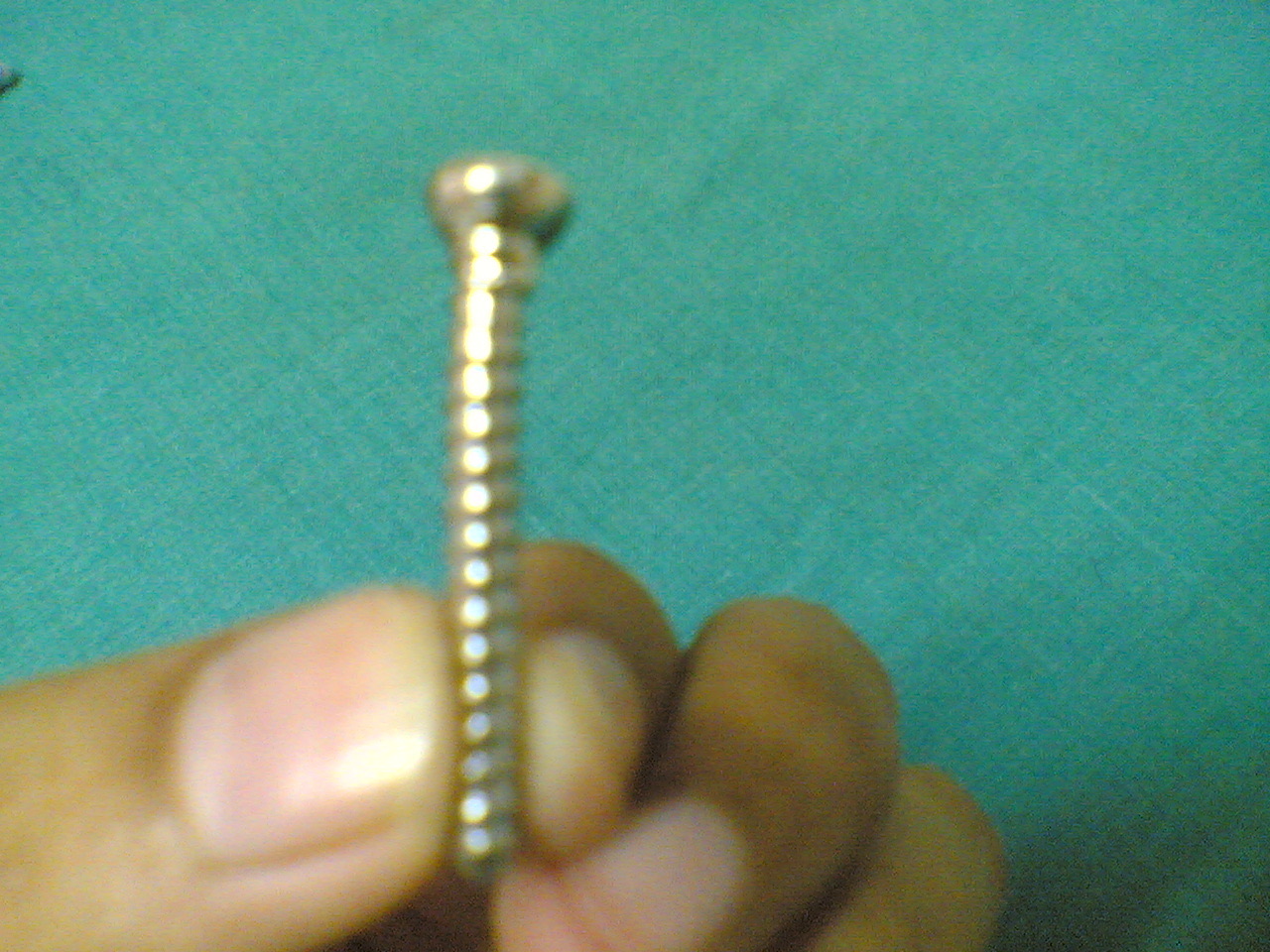
Figure 2. A fully threaded cortical bone screw, with a small pitch and shallow thread for dense diaphyseal bone. Source: Netha Hussain, via Wikimedia Commons, CC BY-SA 3.0.
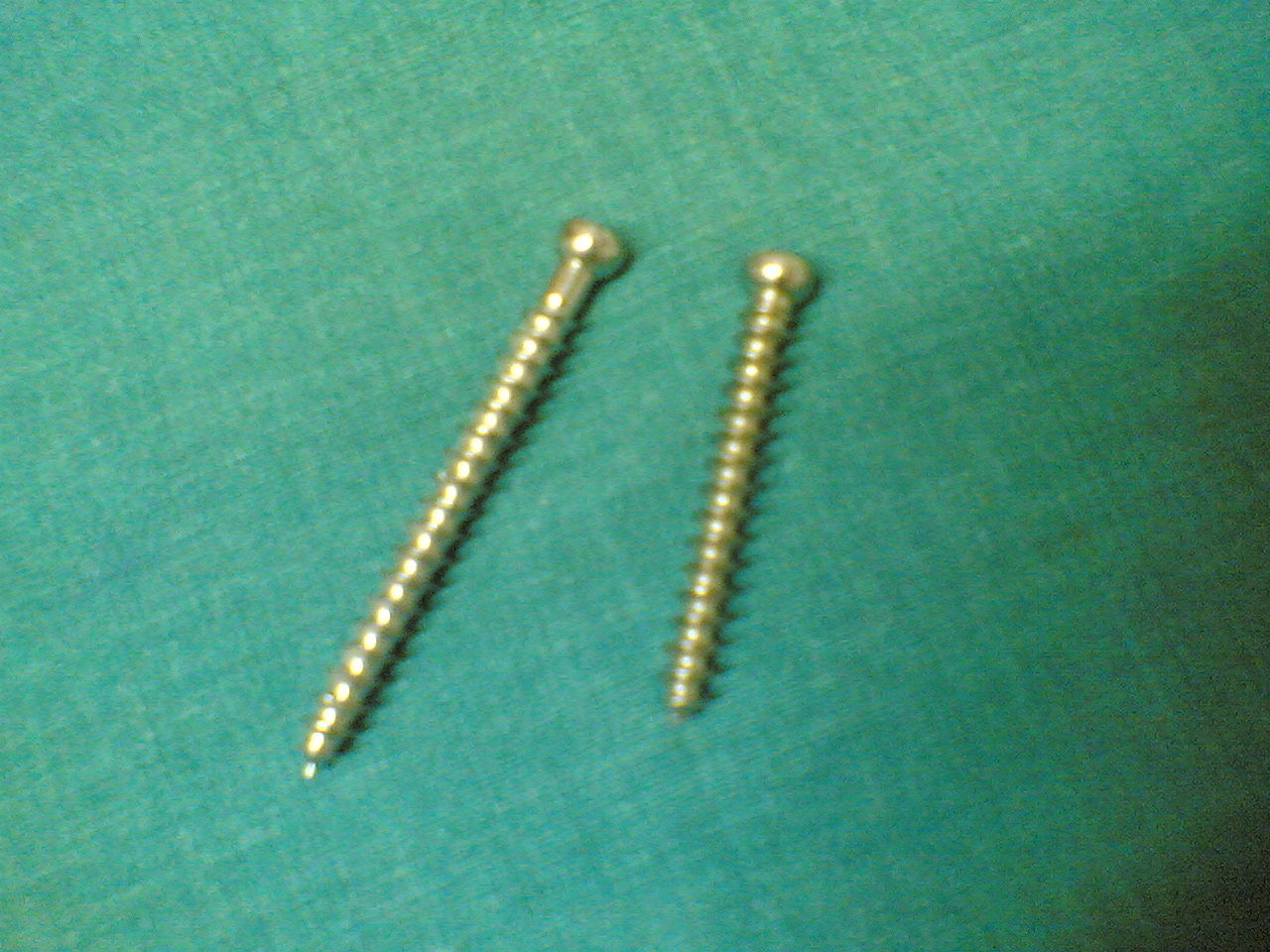
Figure 3. Cancellous bone screws, with a larger pitch and deeper thread for purchase in metaphyseal bone. Source: Netha Hussain, via Wikimedia Commons, CC BY-SA 3.0.
The most important point is functional, not structural: “the term lag screw does not describe screw design but refers to the function of compressing two fragments together.”[34] A screw produces interfragmentary compression only when it has purchase in the far fragment alone and glides freely through the near fragment. There are two ways to achieve this:
- Lag by technique (any fully threaded screw): drill a glide (gliding) hole in the near cortex equal to the screw’s outer/thread diameter, then a thread hole in the far cortex equal to the core diameter, the two holes co-linear and ideally perpendicular to the fracture; countersink the head to spread its load. The thread grips only the far cortex, the head presses the near cortex, and tightening compresses the fracture.[35]
- Lag by design (a partially threaded screw): the smooth shaft is the glide portion and the threads engage the far fragment. The pitfall is unforgiving: if the threaded part crosses the fracture line, no compression occurs and reduction is lost.[36]
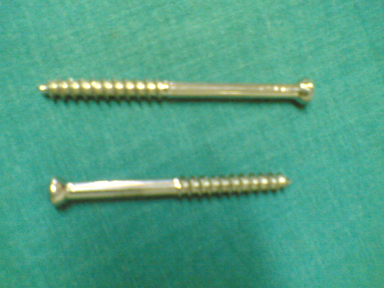
Figure 4. Partially threaded lag screws “by design”: the smooth proximal shank glides through the near fragment while the distal thread grips the far fragment, generating interfragmentary compression. Source: Netha Hussain, via Wikimedia Commons, CC BY-SA 3.0.
A position screw, by contrast, holds two fragments in a fixed relationship without compression (its classic use is the syndesmotic screw at the ankle).[37] A correctly inserted 4.5 mm lag screw in good bone generates substantial force; experts routinely tighten such screws to produce 2,000-3,000 N of axial compression.[38] Screws should be tightened to about two-thirds of the stripping torque, leaving reserve for functional load.[39] When tightening a conventional 4.5 mm screw, only about 40% of the torque becomes axial compression: roughly 50% is lost to friction under the head and 10% to thread friction.[40] A screw inserted through a plate hole can be tightened to nearly twice the torque of an isolated screw, because the plate spreads the head load.[41]
The locking head screw (LHS) is a different mechanism entirely: its threaded head locks into a reciprocally threaded plate hole, forming a fixed-angle couple that does not rely on compressing the plate onto the bone, the same principle as an external fixator.[42] Two rules follow and are repeated emphatically in the source: a locking head screw can never be used as a lag screw, and it cannot be used as a reduction tool.[43] Variable-angle locking screws allow angulation of up to about ±15° from the nominal axis, at the cost of roughly 30% of holding strength (the VA screw holds about 70% of a standard LHS).[44] In vivo loosening of a well-placed conventional screw is caused by micromotion at the thread-bone interface, not by pressure, and a 30% increase in core diameter triples bending resistance.[45]
Part V - Plates and Their Functions
The governing maxim of plating is that “the surgeon, not the designer of the plate, determines how a plate will function.”[46] Any conventional plate can serve any of the recognised functions; the surgeon chooses the function by the way the plate is applied. The AO text lists six plate functions:[47]
- Compression: the plate compresses a simple fracture to achieve absolute stability (e.g. a transverse humeral shaft).
- Protection (neutralisation): the plate neutralises bending and torsional forces to protect a lag screw that is providing the compression (e.g. a simple oblique radial fracture).
- Buttress (antiglide): the plate resists axial load by applying force at 90° to the axis of potential deformity, supporting a metaphyseal split (e.g. a lateral tibial plateau).
- Tension band: placed on the tension (convex) side, the plate converts tensile force into compression at the far cortex (e.g. the olecranon; see Part VI).
- Bridging: the plate spans a comminuted zone, fixed only to the two main fragments, giving relative stability and callus healing.
- Reduction: the plate is used to reduce and hold fragments, temporarily or definitively.
Dynamic compression and prebending
Axial compression through a plate is produced by the dynamic compression principle: the screw hole is shaped like a portion of an inclined cylinder, so the spherical screw head slides down the incline as it is tightened, moving the bone relative to the plate.[48] An eccentric (“load”) drill guide places the hole about 1.0 mm off-centre, away from the fracture, generating compression on tightening, while the neutral guide is offset only about 0.1 mm.[49] A single hole gives up to 1.0 mm of displacement; for more than 2.0 mm an articulated tension device is used.[50] The LC-DCP (limited-contact dynamic compression plate), introduced by Perren in 1990, reduces the plate’s bony footprint (preserving periosteal perfusion) and distributes stiffness evenly so it contours without stress concentration.[51]
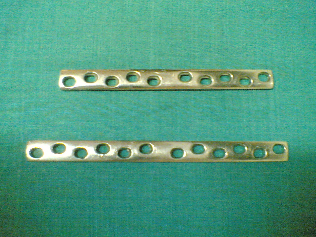
Figure 5. Broad dynamic compression plates, showing the characteristic angled oval holes through which the sliding screw head produces axial compression. Source: Netha Hussain, via Wikimedia Commons, CC BY-SA 3.0.
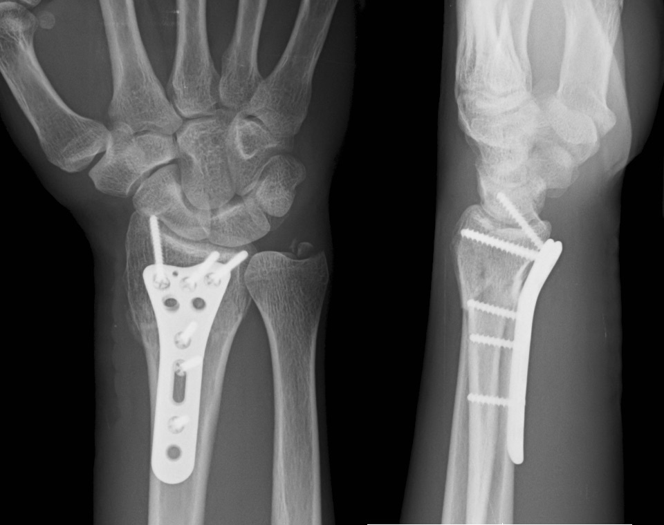
Figure 6. Distal radius fracture fixed with a volar plate and screws (PA and lateral views). Source: Pietz, via Wikimedia Commons, CC BY-SA 4.0.
A subtle but essential technique is prebending (overbending). A straight plate on a straight bone compresses only the near cortex and leaves a gap at the far cortex. Slightly overbending the plate before application means that, as it is tightened straight, it closes the far cortex too, achieving compression across the whole cross-section.[52]
Locking plates and the internal fixator
The locking plate solves the problem that conventional plating depends on friction between plate and bone, which requires the plate to be pressed onto the cortex and so disturbs its blood supply.[53] When the screws lock into the plate, “the plate and screws together act as one unit,” the plate need not touch the bone, and the periosteal vascularity is preserved: the internal fixator principle.[54] The locked construct distributes load across all screws rather than concentrating it at one, so that to fail, all the screws must pull out together with the plate rather than loosening sequentially.[55] Its two strongest indications are osteoporotic bone (a locking screw cannot be overtightened and stripped) and short periarticular segments where a conventional screw would have too short a lever arm.[56] The combination (“combi”) hole of the locking compression plate (LCP) accepts a conventional screw in one half and a locking head screw in the other, allowing hybrid constructs.[57] The cardinal sequence rule is “lag first, lock second”: achieve any interfragmentary or plate-to-bone compression before placing the locked screws.[58] Used with locking screws alone, an LCP can act as a protection, buttress, tension-band or bridge plate, but not as a compression plate or a reduction tool.[59] There is a real hazard of over-stiffness: a locked plate bridging a simple fracture can be too rigid for callus and go on to nonunion, and an incorrect hybrid construct that achieves “neither absolute nor relative stability” produces high strain and fails.[60]
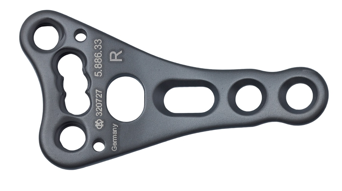
Figure 7. A locking compression plate (LCP), whose combination holes accept either a conventional screw (compression) or a threaded locking head screw (angular stability). Source: Anne Sprechert, via Wikimedia Commons, CC BY-SA 4.0.
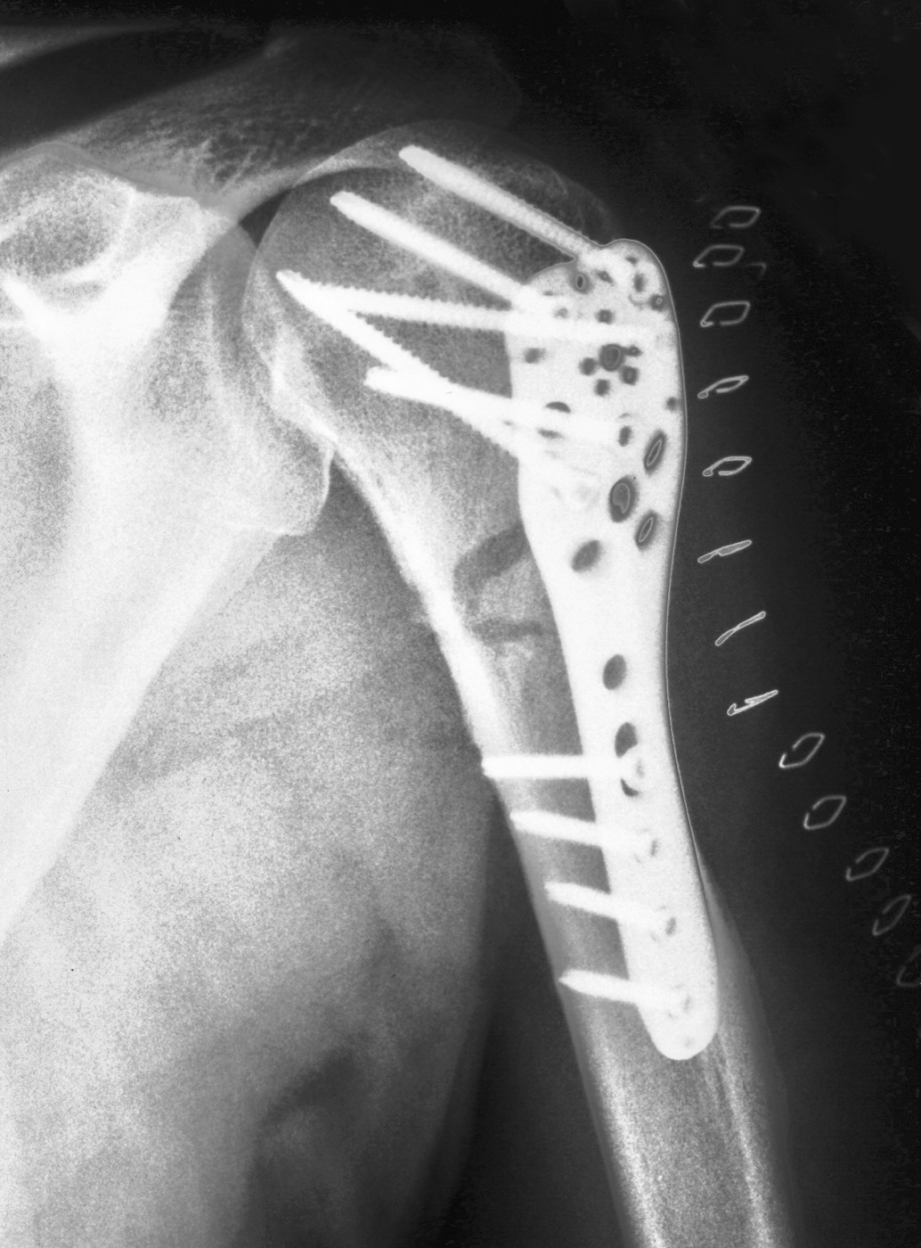
Figure 8. A proximal humeral fracture fixed with an angular-stable locking plate, the divergent locking screws anchoring the head fragment, the classic indication of poor bone stock in a short periarticular segment. Source: Thomas Zimmermann, via Wikimedia Commons, CC BY-SA 3.0 DE.
Quantitative rules for bridge plating
Bridge plating of a comminuted fracture has well-defined biomechanical rules of thumb:[61]
- Use long plates with relatively few, widely spaced screws: a long working length distributes bending stress and lowers the stress per unit area, improving fatigue life.
- Plate span ratio (plate length ÷ fracture length): about 2-3 over a long comminuted zone, up to 4-8 over a short one (and 8-10 for a simple transverse fracture being splinted).
- Plate screw density (screws used ÷ holes) should be kept below about 0.5 in bridging (≤ 0.4-0.5 for multifragmentary, ≤ 0.6-0.8 for simple).
- At least 2-3 screws per main fragment (three is the usual recommendation; four or more in osteoporotic bone), and leave the holes over the fracture empty to lower strain at the plate.
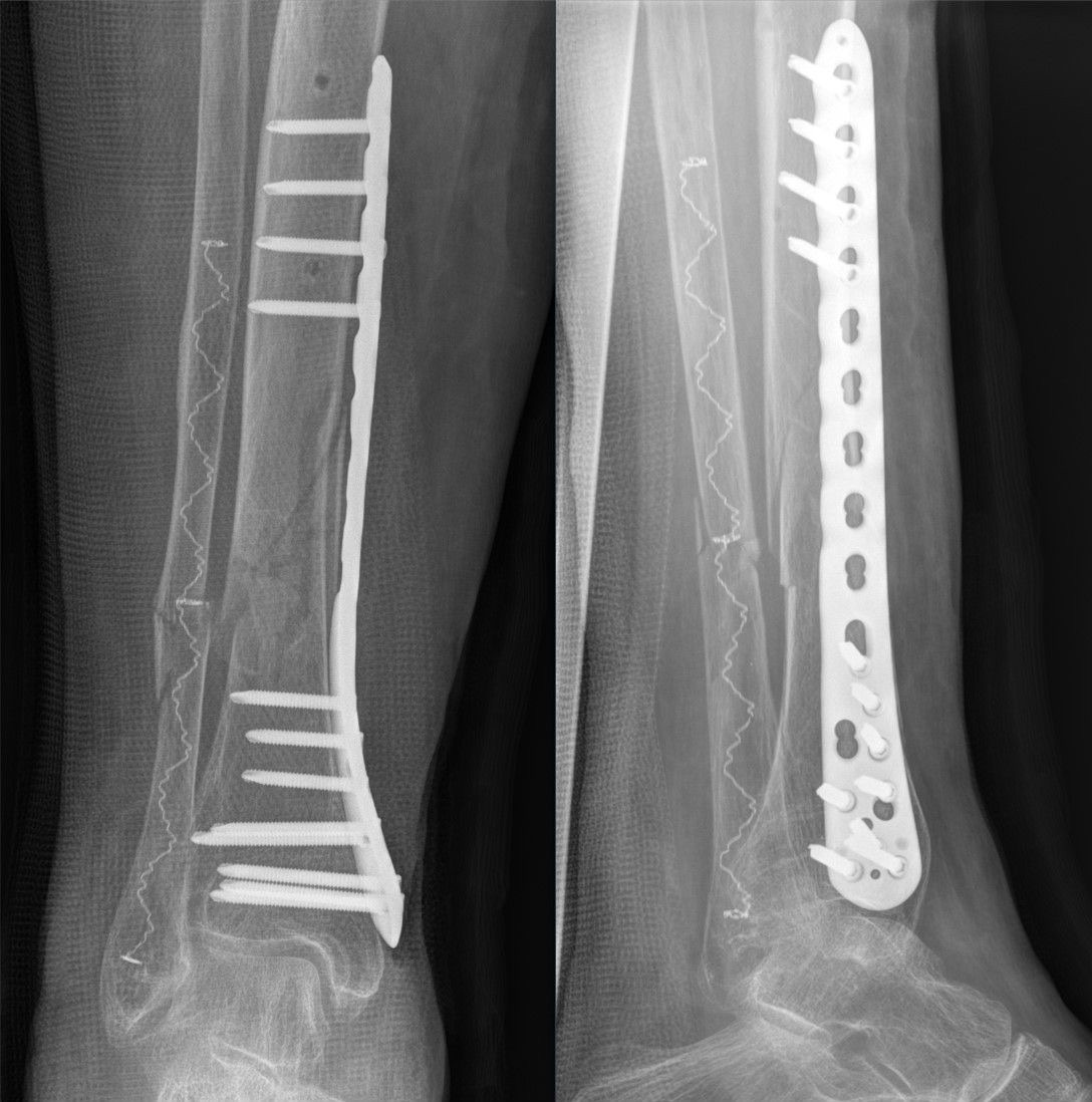
Figure 9. Bridge plating of a comminuted distal-tibia fracture: a long plate spans the fracture, fixed only at the ends with the holes over the comminuted zone left empty, giving relative stability and callus healing. Source: Hellerhoff, via Wikimedia Commons, CC BY-SA 4.0.
Part VI - The Tension Band Principle
The tension band rests on Pauwels’ observation that a curved, eccentrically loaded tubular structure always has a tension side and a compression side.[62] A tension band “converts tensile force into compression force at the opposite cortex” by being applied eccentrically on the convex (tension) side of the bone.[63] Where muscle pull would distract a fragment, the band neutralises that pull and turns it into compression at the fracture surface, and in a dynamic tension band, joint motion increases the compression.[64]
Three prerequisites must hold for a tension band to work:[65]
- The fracture pattern and bone must be able to bear compression.
- There must be an intact cortical buttress opposite the band to resist the compressive force.
- The construct itself must withstand the tensile load.
The second is paramount: a tension band cannot function if the far (concave) cortex is comminuted, because the plate or wire would then bear a bending load and fail by fatigue.[66] The classic applications are the patella and the olecranon (figure-of-eight wire over K-wires, the patella being the textbook dynamic tension band that compresses on knee flexion), and avulsions such as the medial malleolus, greater tuberosity of the humerus and greater trochanter (where it acts as a static tension band).[67] On a diaphysis, the convex side indicates the tension side, so a femoral shaft plate belongs laterally (the tension side under physiological loading), which functions only if the medial cortex is intact to take the compression.[68] The AO text closes with a warning that applies to all metal: “A wire under tension is strong; however, if bending forces are added, it will break due to fatigue. This principle of fatigue failure also holds true for plates.”[69]
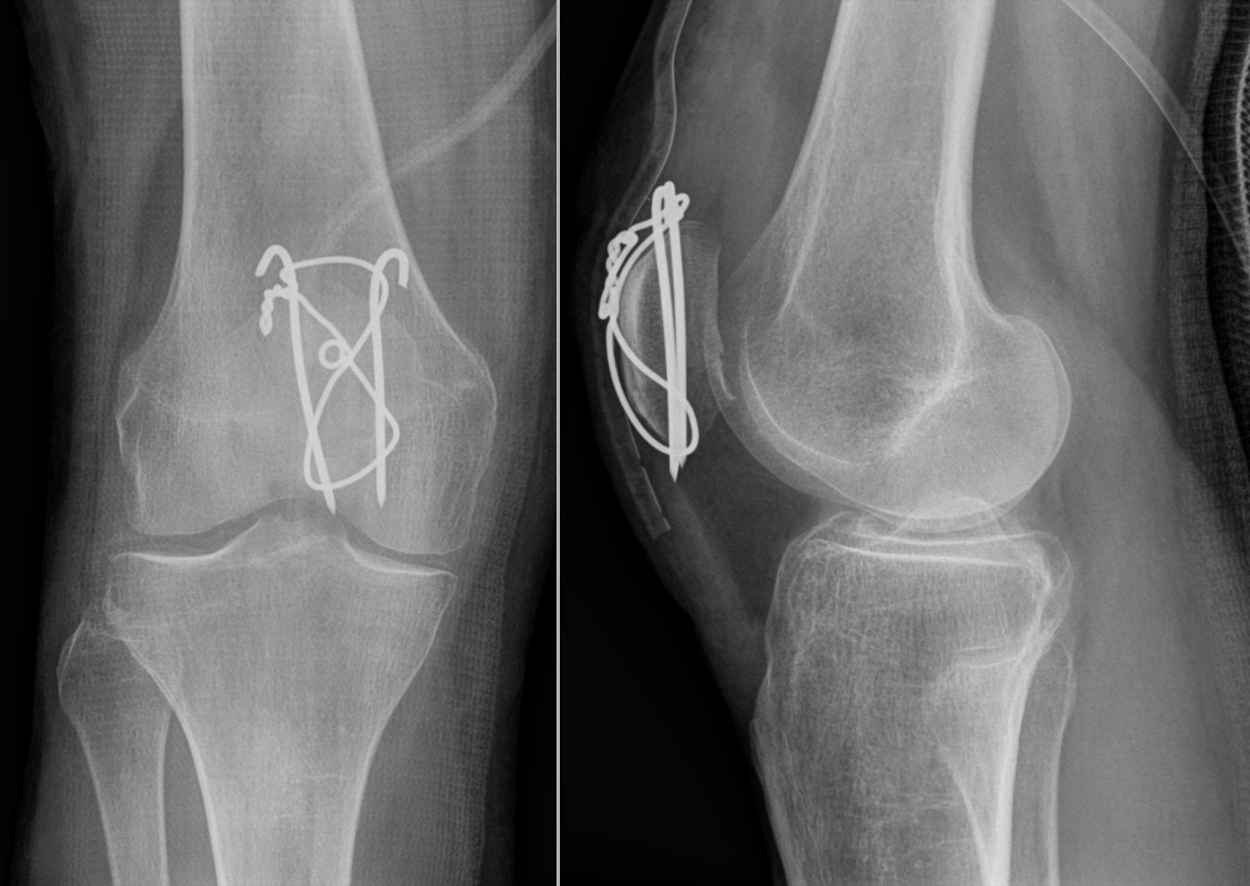
Figure 10. The classic dynamic tension band: a transverse patella fracture fixed with two K-wires and a figure-of-eight wire, so that knee flexion converts the distracting quadriceps pull into compression at the articular surface. Source: Hellerhoff, via Wikimedia Commons, CC BY-SA 3.0.
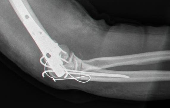
Figure 11. Olecranon tension-band wiring (two K-wires plus a figure-of-eight wire), converting the triceps pull into compression across the fracture. Source: Mehlauge, via Wikimedia Commons, Public Domain.
Part VII - Intramedullary Nailing
The intramedullary nail is a load-sharing internal splint placed along the mechanical axis of the bone, giving relative stability and callus (secondary) healing, and it is the standard treatment for shaft fractures of the femur, tibia and humerus.[70] Its advantages are indirect reduction without opening the fracture, insertion along the loading axis (so the implant is loaded less), a good bone-implant interface, and early load sharing that permits weight-bearing.[71] The design lineage runs from Küntscher’s wartime tight-fitting reamed nail, which relied on press-fit alone, to the locked “universal” nail (Grosse and Kempf’s interlocking screws), whose proximal and distal locking controls length and rotation and so extends nailing to comminuted and more proximal or distal fractures.[72]
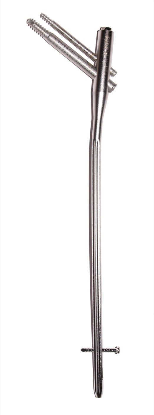
Figure 12. A proximal femoral (cephalomedullary) nail, with cephalic head screws proximally and an interlocking screw distally. Source: Bullenwächter, via Wikimedia Commons, CC BY 3.0.
Reaming: biology and the price of it
Reaming is the central trade-off of nailing. It damages the endosteal (inner cortical) blood supply (reversibly, over about 8-12 weeks) and generates heat that can cause thermal necrosis, raising the infection risk especially in open tibial fractures.[73] But reaming debris is osteogenic and osteoinductive (a local autograft), it increases perfusion of the surrounding soft tissues, and it allows a larger, stiffer nail.[74] The systemic price is fat and marrow embolism: any device introduced into the canal acts as a piston, and intramedullary pressures exceeding the diastolic blood pressure drive marrow content into the venous system and on to the lungs, a particular danger in the patient with chest injury.[75] The embolic load is far higher from the femur than the tibia (78% versus 19% pulmonary intravasation), which is why femoral nailing carries the greater systemic risk.[76] Distal venting of the femur lowers intramedullary pressure by 50-90%, and RIA (reaming-irrigation-aspiration) reduces fat liberation and doubles as a bone-graft harvester.[77] With adequate resuscitation before surgery, modern series show little difference in pulmonary outcome between reamed and unreamed femoral nailing. Still, reamed nailing remains the gold standard for the isolated femoral shaft, and unreamed femoral nailing carries a markedly higher nonunion rate (one RCT found a 4.5-fold relative risk).[78]
Locking, working length and dynamisation
Static interlocking (locking both proximally and distally) is the current standard for diaphyseal fractures because it controls both length and rotation, and it does not compromise union.[79] At least two distal interlocking screws are advised, because a single screw allows the nail to “toggle”.[80] The working length of a nail is the unsupported span between its fixation points: at the isthmus a reamed nail’s contact with the endosteum sets the fixation points and the working length is short and stiff, whereas in the metaphysis the interlocking screws become the fixation points.[81] Bending stiffness is inversely proportional to the square of the working length, and the fatigue strength of the construct rises with the diameter of the interlocking screws.[82] Dynamisation (removing the static screws from one segment so a screw in an oval hole still controls alignment while allowing axial impaction) speeds healing in delayed union (best at about 2-3 months) but is not used for acute fractures.[83] In metaphyseal fractures, where the wide canal invites malalignment, Poller (blocking) screws placed beside the nail narrow its path, push it central and convert shear into compression.[84] For nonunion, exchange nailing with a reamed nail one or two millimetres larger is highly effective, especially in the tibia.[85]
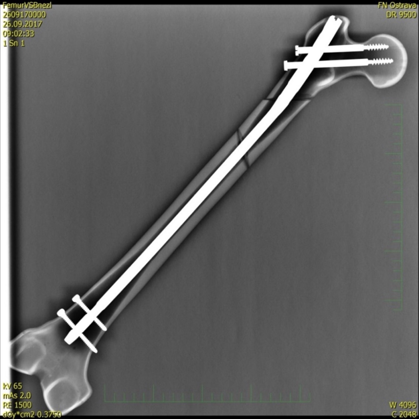
Figure 13. A femoral shaft fracture fixed with an antegrade intramedullary nail and proximal and distal interlocking screws. Source: Fry72 / Karel Frydrýšek, via Wikimedia Commons, CC BY-SA 4.0.
Part VIII - External Fixation
The external fixator stabilises a fracture from outside the limb through transcutaneous pins, giving relative stability and callus healing while leaving the zone of injury largely undisturbed.[86] It is “one of the mainstays of operative fracture treatment,” valued for rapid emergency application, minimal added soft-tissue insult, the ability to adjust reduction without further surgery, and minimal foreign material in the presence of infection.[87] Its components are Schanz screws (half-pins) and transfixion (Steinmann) pins as bone anchors, rods or tubes as longitudinal connectors (the large 11 mm, medium 8 mm, small 4 mm and a 2 mm “mini” system for the hand), and clamps joining pin to rod and rod to rod.[88]
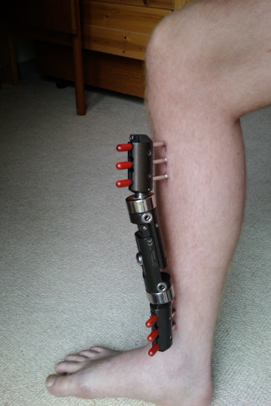
Figure 14. A tibia in a monolateral (uniplanar) external fixator: Schanz half-pins above and below the fracture connected to a single longitudinal bar. Source: Redhead.dk, via Wikimedia Commons, CC BY 3.0.
Frame stiffness
Frame stiffness is governed by a short, reliable list of variables:[89]
- Pin diameter: bending stiffness rises with the fourth power of the pin radius (so 6 mm pins are about twice as stiff as 5 mm); the practical adult maximum is about 6 mm, and a pin hole exceeding 20-30% of the bone diameter risks a stress fracture through the hole.
- Number of pins: more pins give a stiffer frame (three rather than two per side in osteopenic bone).
- Pin spread: pins as widely separated as possible within each main fragment increase rigidity.
- Pin proximity to the fracture: pins close to the fracture (but outside the zone of injury) shorten the working length.
- Bone-to-rod distance: keep the connecting rod as close to the bone as possible.
- Number and stacking of rods: double-stacking markedly increases stiffness (in one knee-spanning construct, AP bending rose 109%, axial compression 150%).
- Configuration: stiffness increases from uniplanar to A-frame to biplanar; a “delta” frame (two four-pin frames at 90°) is the most rigid.
A crucial caveat is that a monolateral frame can almost never achieve the absolute rigidity needed for primary healing, and that excessive rigidity can itself delay healing, which is why progressive weight-bearing is the best dynamisation.[90]
Configurations, pin care and special uses
Beyond the unilateral/uniplanar frame (the workhorse for the acute diaphyseal fracture), the hybrid fixator combines a tensioned fine-wire ring near a joint with diaphyseal half-pins for periarticular fractures, and the circular (Ilizarov) ring fixator uses tensioned thin wires through rings to give multiplanar stability, including stable fixation even in osteopenic bone, because tensioned wires avoid the continuous cortical resorption that loosens half-pins.[91] The modern hexapod (Taylor Spatial) frame connects two rings by six oblique struts whose computer-calculated lengthening corrects deformity in all planes at once.[92] The recurring complication is the pin track: thermal necrosis at insertion produces a “ring sequestrum” and loosening, so pins are predrilled and inserted by hand with cooling, and pin sites need a clear nursing protocol.[93] When converting a temporary fixator to internal fixation, do it early, within about two weeks, and treat any pin site older than 10-14 days as colonised, debriding it (with a “pin holiday” if there is any doubt) before placing an implant.[94] The Ilizarov principle of distraction osteogenesis, slow distraction of an osteotomy at about 0.5-1 mm per day, preserving the periosteum so new bone forms in the gap, underlies limb lengthening and segmental bone transport; distract too fast and the strain exceeds tissue tolerance and no bone forms.[95]
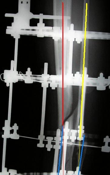
Figure 15. A tibia in an Ilizarov circular (ring) fixator: rings connected by threaded rods and stabilised by tensioned transfixion wires, the construct that gives stable fixation even in osteopenic bone and enables distraction osteogenesis. Source: Viapastrengo, via Wikimedia Commons, CC BY-SA 3.0.
Part IX - Biomechanics of Fixation: A Summary
Two ideas tie the implants together. The first is load-sharing versus load-bearing. An implant that carries the majority of the load will eventually fail by fatigue if union is delayed: “all implants will fail after experiencing a critical number of stress cycles prior to fracture healing.”[96] Anatomical reduction with cortical apposition lets the bone share the load, dramatically lowering the stress in the implant; a persistent fracture gap turns the plate into the sole load path and the fracture into a fulcrum that bends and breaks it.[97] Fatigue is the product of load and cycles: stresses below the static failure limit still propagate microcracks to catastrophic failure, and the endurance limit is the stress that can be borne indefinitely.[98] A vivid illustration: non-locked screws tightened to only 10-15% below full torque fail in fewer than 1,000 cycles, against more than 2.5 million cycles when fully tightened.[99]
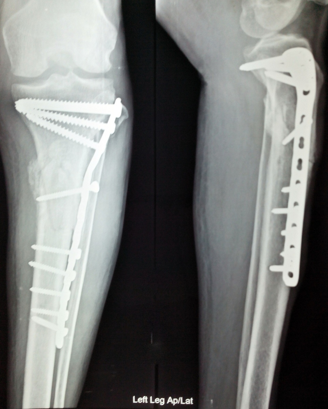
Figure 16. A proximal tibial (plateau) fracture fixed with a long lateral buttress/locking plate and screws; once the fracture is reduced the bone shares the load with the implant. Source: Nizil Shah, via Wikimedia Commons, CC BY-SA 4.0.
The second is stiffness, which depends on both material and geometry. Implant stiffness scales with the elastic modulus (titanium ≈ half of steel), so geometry is the surgeon’s lever: a plate’s bending stiffness scales with the cube of its thickness, while the bending stiffness of a nail, screw or pin scales with the fourth power of its radius: a 6 mm screw is about sixteen times as stiff as a 3 mm screw.[100] Working length is the distance between the nearest points of fixation on either side of the fracture, and stability is inversely proportional to it: a longer working length is more flexible but more durable (lower peak strain), which is exactly what a bridge construct wants.[101] Stress risers (empty screw holes over a fracture, the end of a plate, the junction of a hip stem and a nail) concentrate stress and are where implants break.[102] Pull-out strength of a screw rises with diameter, thread density, embedded length and bone density, but in cancellous bone insertional torque is the more meaningful measure, and tapping cancellous bone reduces pull-out by 8-27% (so drill, do not tap).[103] The recurring modern theme is that the optimum stiffness for healing is lower than that of a standard locked construct, and a construct that is too stiff fails to form callus.[104]
Part X - Removal of Osteosynthesis Hardware
Implant removal is one of the commonest elective orthopaedic operations, but it is not without risk, and the evidence base is thin. The key principle is that routine removal of asymptomatic hardware is not recommended in adults; removal is reserved for a clear indication.[105] The accepted indications are symptomatic or prominent hardware causing pain or soft-tissue irritation (subcutaneous plates over the malleoli, the olecranon, the clavicle, the distal tibia), infection of the implant, mechanical failure or breakage, the need to remove an implant before revision surgery or joint replacement, intra-articular or tendon-impinging hardware, and the paediatric patient, in whom buried implants may become overgrown and in whom routine removal is far more common than in adults.
When removal is undertaken, timing should await solid radiographic and clinical union, generally at least 12 months and often 18-24 months for diaphyseal plates, because the bone beneath a plate remodels slowly. The chief hazard is refracture, which is highest after removal of forearm and other diaphyseal plates (through the residual screw holes, which act as stress risers until they remodel), so protected loading is advised for several weeks after removal. Other risks include neurovascular injury during dissection through scar, incomplete removal from broken or cold-welded screws (titanium is especially prone to cold-welding of the locking head to the plate), and a fresh wound and anaesthetic for what is often a comfort indication. The standard counsel, therefore, is to remove hardware only when the benefit is clear and to warn the patient explicitly of the refracture risk.
References
-
Synthesised from the operative-indication discussion in Rockwood & Green 9e ch.11 (Bishop, Behn & Gardner), p.641, and the non-operative-versus-operative framing of Topic 3; this list is standard orthopaedic teaching.
-
AO Principles of Fracture Management 3e (Buckley, Moran & Apivatthakakul, eds.) p.243.
-
AO 3e p.240; Rockwood 9e p.543.
-
AO 3e p.240.
-
AO 3e p.240. The base-excess value is printed in the source as “BE
5.5 mmol/L”, which physiologically denotes a base-deficit limit.
-
The four AO/ASIF principles are standard teaching; Rockwood 9e ch.11 frames them functionally rather than reciting them as a list (p.641), and the dedicated “AO philosophy” chapter was not present in the mined AO extract - see the absolute-stability source note. The canonical statement is given here for completeness.
-
Rockwood 9e pp.661, 664-665; AO 3e p.205.
-
Rockwood 9e pp.664-665.
-
AO 3e pp.205, 218; Rockwood 9e pp.652-656.
-
AO 3e p.205.
-
AO 3e p.205.
-
AO 3e p.205; Rockwood 9e pp.643, 661.
-
Rockwood 9e pp.662-663; AO 3e pp.47-48.
-
AO 3e pp.47-48; Rockwood 9e p.663.
-
Rockwood 9e p.663.
-
Rockwood 9e p.663.
-
AO 3e p.262; Rockwood 9e p.664.
-
Rockwood 9e pp.663-664.
-
Rockwood 9e p.664.
-
AO 3e p.47.
-
AO 3e p.47; Rockwood 9e p.674.
-
AO 3e p.47; Rockwood 9e p.675, Table 11-1.
-
AO 3e pp.47-48; Rockwood 9e p.672.
-
Rockwood 9e p.676; AO 3e p.48.
-
AO 3e pp.48, 205.
-
AO 3e pp.49-50.
-
AO 3e p.52.
-
AO 3e p.53.
-
AO 3e pp.50-51.
-
AO 3e p.193.
-
AO 3e p.193; Rockwood 9e p.646.
-
Rockwood 9e p.646.
-
AO 3e p.197; Rockwood 9e p.648.
-
AO 3e p.193.
-
AO 3e pp.199-200; Rockwood 9e pp.648-649.
-
AO 3e p.200; Rockwood 9e p.658, Fig 11-7.
-
AO 3e p.193, Table 3.2.1-1.
-
AO 3e pp.201, 218.
-
AO 3e p.201.
-
AO 3e p.195.
-
AO 3e p.196.
-
AO 3e p.193.
-
AO 3e pp.203-204.
-
AO 3e pp.214, 291.
-
AO 3e pp.202-203.
-
AO 3e p.206.
-
AO 3e p.206, Table 3.2.2-1; Rockwood 9e pp.652-662.
-
AO 3e pp.207-208.
-
AO 3e p.209.
-
AO 3e p.208.
-
AO 3e pp.206-207.
-
AO 3e pp.220-221; Rockwood 9e p.653, Fig 11-13.
-
AO 3e p.289.
-
AO 3e p.292; Rockwood 9e p.669.
-
AO 3e pp.292, 296; Rockwood 9e p.669.
-
AO 3e pp.292, 298.
-
AO 3e pp.291, 307.
-
AO 3e p.308.
-
AO 3e p.308.
-
AO 3e pp.262, 307; Rockwood 9e p.664.
-
AO 3e pp.224, 308, Table 3.3.4-3; Rockwood 9e p.672.
-
AO 3e p.229.
-
AO 3e p.229.
-
AO 3e pp.230-231.
-
AO 3e p.235.
-
AO 3e pp.223-224; Rockwood 9e p.658.
-
AO 3e pp.231, 233.
-
AO 3e pp.224, 232; Rockwood 9e pp.659-660.
-
AO 3e p.236.
-
AO 3e p.237; Rockwood 9e p.643.
-
AO 3e p.237.
-
AO 3e pp.237-238.
-
AO 3e p.238.
-
AO 3e p.238.
-
AO 3e p.239.
-
AO 3e p.241.
-
AO 3e p.239.
-
AO 3e p.240; Rockwood 9e p.643.
-
Rockwood 9e p.644.
-
AO 3e p.257.
-
Rockwood 9e pp.664, 667.
-
Rockwood 9e p.667; AO 3e p.258.
-
AO 3e p.258; Rockwood 9e p.644.
-
AO 3e pp.249-250.
-
Rockwood 9e p.645.
-
AO 3e p.273.
-
AO 3e p.273.
-
AO 3e pp.280-281; Rockwood 9e p.549.
-
AO 3e p.275; Rockwood 9e pp.552, 559, 561-562.
-
Rockwood 9e p.550; AO 3e pp.275, 287.
-
AO 3e pp.281-282; Rockwood 9e p.555.
-
AO 3e p.282; Rockwood 9e p.548.
-
AO 3e pp.275-276, 286-287; Rockwood 9e p.556.
-
AO 3e pp.287-288.
-
AO 3e p.286.
-
Rockwood 9e pp.673, 680.
-
Rockwood 9e pp.672, 681.
-
Rockwood 9e p.673.
-
Rockwood 9e p.681.
-
Rockwood 9e pp.672, 675, 677.
-
Rockwood 9e pp.664, 672.
-
Rockwood 9e pp.665, 684.
-
Rockwood 9e pp.678-679.
-
Rockwood 9e p.672.
-
Removal of osteosynthesis hardware is not addressed in the mined Rockwood or AO extracts (which cover only incidental broken-screw and pin-removal technique); this section is standard orthopaedic teaching, flagged as supplementary.
-
Standard AO/ASIF teaching; Rockwood 9e p.641 frames these functionally.
-
AO 3e pp.205, 218.
-
Rockwood 9e p.663; AO 3e p.262.
-
AO 3e pp.199-201.
-
AO 3e p.206.
-
AO 3e pp.229, 235.
-
AO 3e pp.289, 292, 308.
-
AO 3e pp.238-241.
-
AO 3e p.275; Rockwood 9e pp.552, 561-562.
-
Rockwood 9e pp.664, 667.
-
Rockwood 9e pp.665, 673, 684.
-
AO 3e p.286.
-
Standard teaching; not covered in the mined extracts.