Contents
- Part I - Biomaterials
- Part II - Biomechanics and Tribology
- Part III - Bearing Surfaces and Wear
- Part IV - Osteolysis and Aseptic Loosening
- Part V - Implant Fixation
- Part VI - Complications
- Part VII - Total Knee Arthroplasty: Principles
- References
Part I - Biomaterials
A joint replacement is a composite of materials with very different stiffness: metal, polymer, ceramic and (in cemented constructs) acrylic, bridging the gap from a rigid implant to comparatively flexible bone. Arthroplasty turns on choosing and combining these materials so that load is transmitted, motion is restored, and wear and loosening stay low over decades. The single most important physical property is the elastic (Young’s) modulus, which ranks (low to high): trabecular bone (~0.1 GPa) < UHMWPE (~1) < PMMA cement (~1-4) < cortical bone (~17) < titanium alloy (~105) < cobalt-chromium (~210-240) < alumina ceramic (~400).[1]
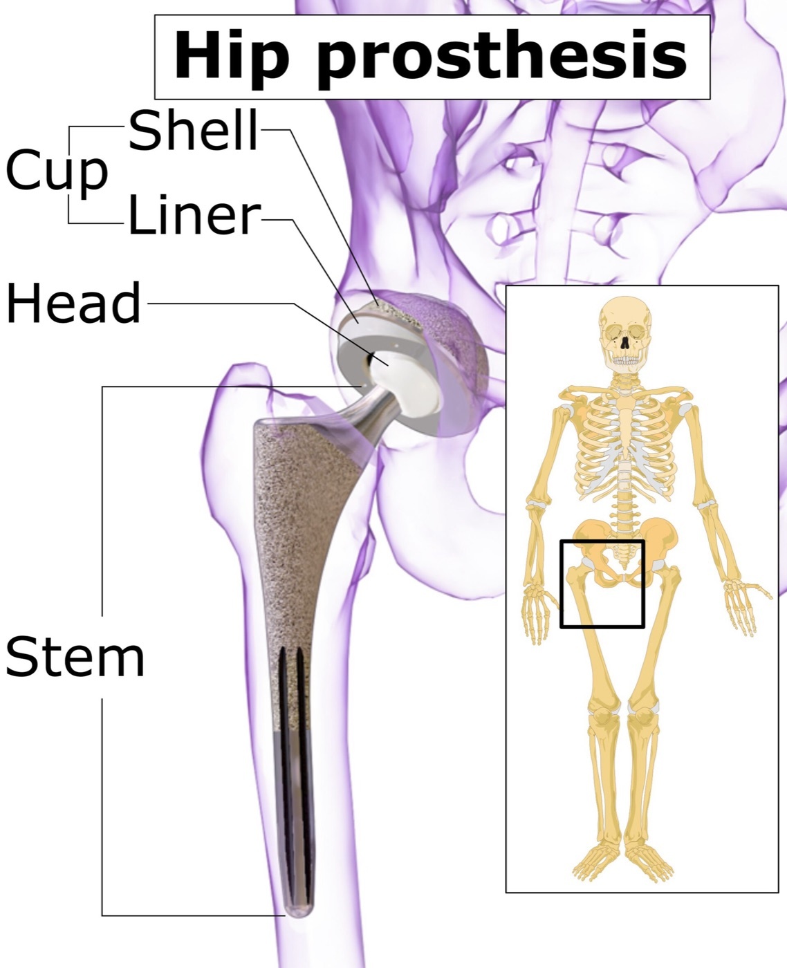
Figure 1. Components of a total hip prosthesis: acetabular shell and liner, femoral head, and stem. Source: Mikael Häggström (using a source image by BruceBlaus), via Wikimedia Commons, CC BY-SA 4.0.
Figure 1. Components of a total hip prosthesis: acetabular shell and liner, femoral head, and stem. Source: Mikael Häggström (using a source image by BruceBlaus), via Wikimedia Commons, CC BY-SA 4.0.
Metals
Three alloy systems are used. Stainless steel (316L) is now largely historical, being more prone to pitting and crevice corrosion. Cobalt-chromium (CoCr) alloys (cast ASTM F75 “Vitallium”; the stronger wrought form) are hard, wear-resistant and corrosion-resistant, which is why they serve for femoral heads and metal bearings. Titanium alloys (Ti-6Al-4V) have the most stable oxide film (best corrosion resistance) and a modulus closest to bone, but they are notch-sensitive and wear poorly, so titanium is used for stems, not bearing surfaces.[2] Modularity introduces taper (trunnion) corrosion / fretting (“trunnionosis”) at the head-neck junction, where mechanically shed oxide acts as third-body debris. A CoCr head on a titanium stem is electrochemically acceptable, but stainless steel must not be coupled with either.[3]
Polyethylene
Ultra-high-molecular-weight polyethylene (UHMWPE) is the classic acetabular/tibial bearing. Its weakness is that gamma sterilisation in air generates free radicals that drive oxidation and embrittlement (the historical cause of catastrophic shelf-aged liner failure). Highly cross-linked polyethylene (HXLPE) is made by higher-dose irradiation to cross-link the chains, which reduces wear by roughly 40-95%; the trapped free radicals are then removed by remelting (most effective, slight loss of mechanical properties) or annealing (retains properties but leaves residual radicals), or scavenged by adding vitamin E.[4]
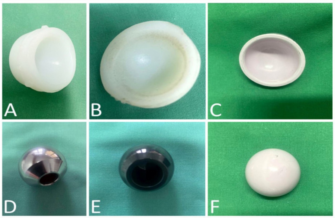
Figure 2. Bearing components: (A) cross-linked and (B) conventional polyethylene liners, (C) ceramic liner, (D) cobalt-chrome head, (E) oxidised-zirconium head, (F) ceramic head. From Savin et al. (2023), Polymers 15:3278, PMC10422432, Fig. 2, CC BY 4.0.
Figure 2. Bearing components: (A) cross-linked and (B) conventional polyethylene liners, (C) ceramic liner, (D) cobalt-chrome head, (E) oxidised-zirconium head, (F) ceramic head. From Savin et al. (2023), Polymers 15:3278, PMC10422432, Fig. 2, CC BY 4.0.
Ceramics
Alumina (Al₂O₃) and zirconia (ZrO₂), and the composite zirconia-toughened alumina (ZTA / Biolox Delta), are extremely hard, wettable (well-lubricated) and inert, which gives the lowest wear of any bearing. The price is that they are brittle with a finite fracture risk.[5]
PMMA bone cement
Polymethylmethacrylate is supplied as a powder (PMMA beads, the initiator benzoyl peroxide, a radiopacifier ± antibiotic) and a liquid monomer (MMA with the activator DMPT and an inhibitor); mixing triggers free-radical polymerisation through mixing → waiting → application → setting phases.[6] The reaction is exothermic (~52 kJ/mol; bench peak 80-90 °C, lower in vivo), which can approach the bone-necrosis threshold of 50 °C for 1 minute / 47 °C for 5 minutes.[7] The key point is that cement is a grout, not a glue: it has no adhesive properties and fixes by mechanical interlock. Because its strength is about twice as great in compression as in tension or shear, implants should be designed to load the mantle in compression.[8]
Part II - Biomechanics and Tribology
Biomechanics of the replaced hip
The hip carries a joint reaction force of several times body weight (rising on stairs and with stumbling), balanced by the abductors acting across a lever arm. Two reconstruction parameters dominate. Restoring the centre of rotation to its anatomical (especially medial) position lowers the contact force, and restoring femoral offset lengthens the abductor lever, which reduces the joint force and improves stability (at the cost of higher bending on the stem); reduced offset increases polyethylene wear.[9] A larger femoral head increases the range of motion before impingement and improves stability, but increases volumetric wear. That is the central design trade-off.[10]
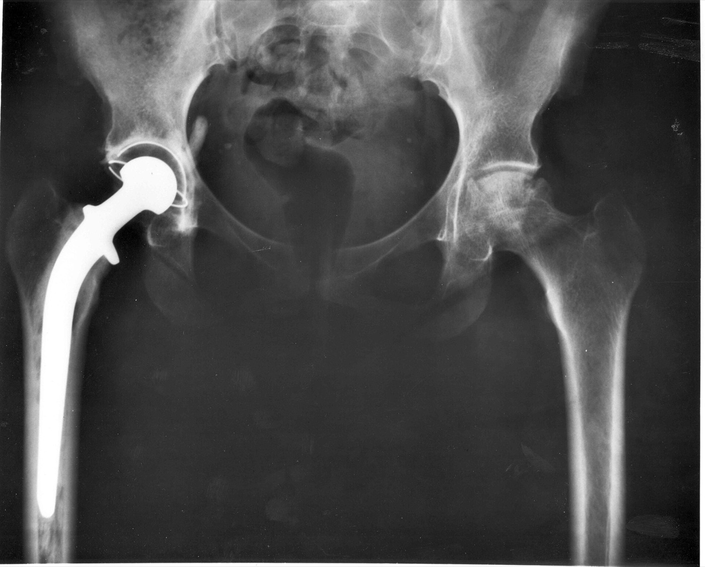
Figure 3. AP pelvic radiograph of a total hip replacement in situ (acetabular cup, head and femoral stem). Source: NIH / NIADDK, via Wikimedia Commons, public domain.
Figure 3. AP pelvic radiograph of a total hip replacement in situ (acetabular cup, head and femoral stem). Source: NIH / NIADDK, via Wikimedia Commons, public domain.
Charnley’s low-friction arthroplasty
John Charnley’s foundational principle was low frictional torque. He paired a small 22.225 mm femoral head with a thick polyethylene cup, because the frictional torque transmitted to the cup-bone interface is proportional to head radius, so a small head minimises the torque that would otherwise loosen the cement.[11]
Tribology - friction, lubrication and wear
Tribology is the science of interacting surfaces in relative motion (friction, lubrication, wear). Contact occurs only at microscopic asperities, so the real contact area is tiny. Lubrication is described by the lambda (λ) ratio (film thickness ÷ surface roughness), which defines three regimes: **boundary (λ < 1, asperities touch), mixed (1 < λ < 3), and fluid-film/hydrodynamic (λ
3, surfaces fully separated)**.[12] Real implants operate mostly in the boundary/mixed regime, so wear particles are always generated. The four wear mechanisms are adhesion, abrasion, surface fatigue (delamination/pitting), and tribochemical/corrosive wear, and McKellop’s four wear modes describe where wear occurs (mode 1 = intended bearing surfaces; mode 2 = bearing against a non-bearing surface through a worn liner; mode 3 = third-body particles; mode 4 = backside/fretting at non-bearing surfaces).[13]
Part III - Bearing Surfaces and Wear
The bearing couple is chosen for its wear behaviour. Metal-on-polyethylene (MoP) is the clinical baseline, with a linear wear rate of about 0.1-0.2 mm/yr; ceramic-on-polyethylene (CoP) reduces this. Highly cross-linked polyethylene against metal or ceramic cuts wear by more than half again. The hard-on-hard bearings give the lowest wear: ceramic-on-ceramic (CoC) wears up to thousands of times less than MoP, and metal-on-metal (MoM) 40-100 times less.[14]
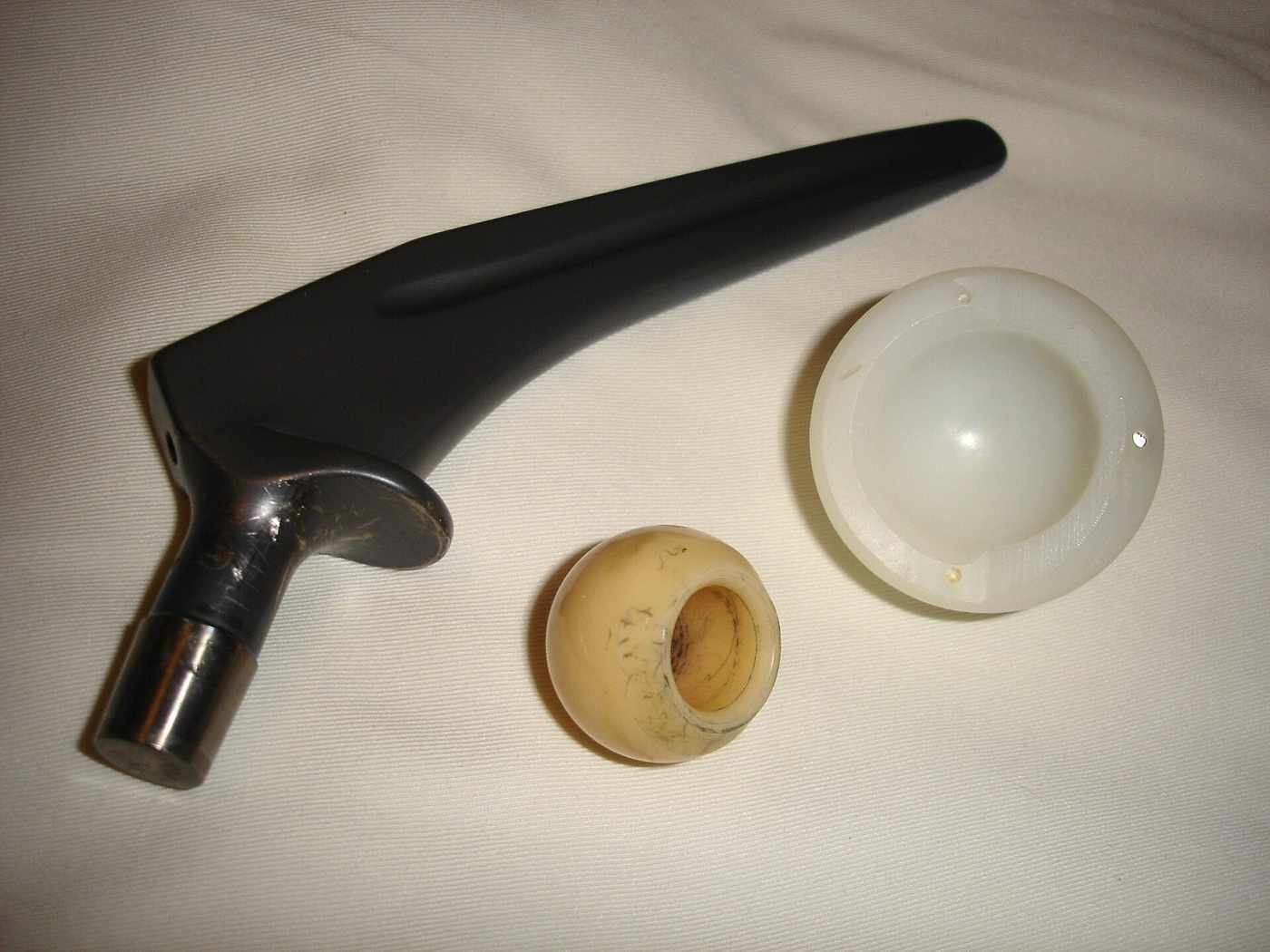
Figure 4. A disassembled hip prosthesis showing the bearing couple: femoral stem, head (with surface wear), and polyethylene cup. Source: Wikimedia Commons, public domain.
Figure 4. A disassembled hip prosthesis showing the bearing couple: femoral stem, head (with surface wear), and polyethylene cup. Source: Wikimedia Commons, public domain.
One quantitative point distinguishes linear from volumetric wear and explains the head-size paradox: in MoP, volumetric wear rises ~4-6% per millimetre of head diameter (longer sliding distance), whereas in MoM a larger head lowers wear by improving fluid-film lubrication.[15]
Each hard bearing has a characteristic failure mode:
- Ceramic-on-ceramic: lowest wear and inert debris, but fracture (a surgical emergency requiring revision), squeaking, and stripe wear from edge loading/microseparation.[16]
- Metal-on-metal: very low wear but release of cobalt and chromium ions and adverse local tissue reactions (ALTR/ARMD), including ALVAL and pseudotumours, a delayed-type hypersensitivity-like response. These drove high revision rates and implant recalls (e.g. the ASR); MoM is contraindicated in renal failure and avoided in women of childbearing age.[17]
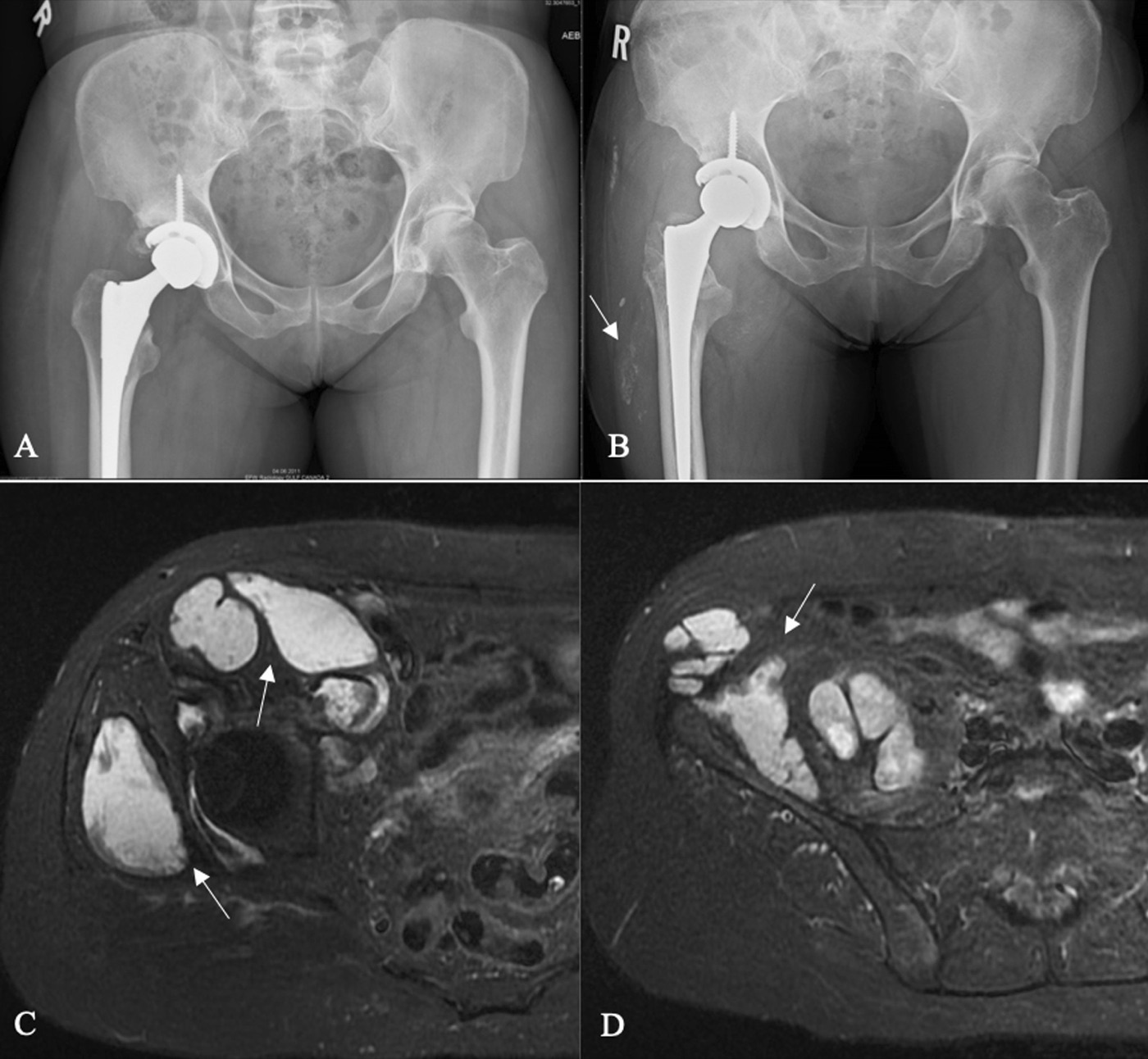
Figure 5. Adverse local tissue reaction to metal debris: AP radiographs (A, B) and axial MRI (C, D) showing a cystic pseudotumour mass around a hip arthroplasty. From Mastel et al. (2022), J Med Case Reports 16:115, PMC8941771, Fig. 1, CC BY 4.0.
Figure 5. Adverse local tissue reaction to metal debris: AP radiographs (A, B) and axial MRI (C, D) showing a cystic pseudotumour mass around a hip arthroplasty. From Mastel et al. (2022), J Med Case Reports 16:115, PMC8941771, Fig. 1, CC BY 4.0.
Part IV - Osteolysis and Aseptic Loosening
Aseptic loosening driven by particle disease is the commonest mode of long-term failure, and it is dominated by polyethylene wear debris, not cement (the original “cement disease” was a misattribution).[18]
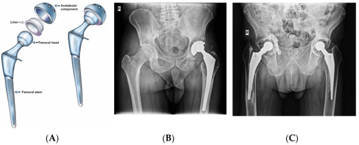
Figure 6. Total hip arthroplasty: (A) labelled components; (B) polyethylene wear/particle disease 15 years after a cementless metal-on-polyethylene THA; (C) aseptic loosening of a cemented THA. From Savin et al. (2023), Polymers 15:3278, PMC10422432, Fig. 1, CC BY 4.0.
Figure 6. Total hip arthroplasty: (A) labelled components; (B) polyethylene wear/particle disease 15 years after a cementless metal-on-polyethylene THA; (C) aseptic loosening of a cemented THA. From Savin et al. (2023), Polymers 15:3278, PMC10422432, Fig. 1, CC BY 4.0.
The osteolysis cascade is high-yield: submicron (≈0.1-1 µm) polyethylene particles are phagocytosed by macrophages → release of pro-inflammatory cytokines (TNF-α, IL-1, IL-6, PGE₂) and upregulation of RANKL → osteoclast differentiation and activation → periprosthetic bone resorption (osteolysis) → loosening.[19] Debris reaches any region the pressurised joint fluid can access, Schmalzried’s “effective joint space”, which explains osteolysis remote from the bearing.[20] Osteolysis correlates with the wear rate: it essentially does not occur below about 0.1 mm/yr and is near-universal above 0.3 mm/yr (the “osteolysis threshold”).[21]
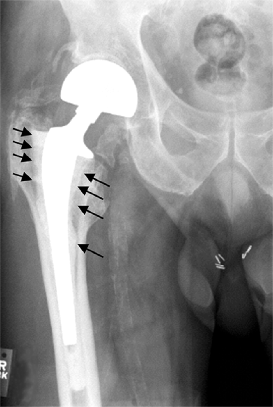
Figure 7. Periprosthetic osteolysis: radiolucent peri-implant bone loss along the femoral shaft (arrows) of a cemented stem - aseptic loosening. From Shen et al. (2006), Arthritis Research & Therapy, via Wikimedia Commons, CC BY 2.0.
Figure 7. Periprosthetic osteolysis: radiolucent peri-implant bone loss along the femoral shaft (arrows) of a cemented stem - aseptic loosening. From Shen et al. (2006), Arthritis Research & Therapy, via Wikimedia Commons, CC BY 2.0.
Part V - Implant Fixation
Cemented fixation
PMMA fixes by mechanical microinterlock (grout, not glue): the bone is prepared (reamed through subchondral bone, pulsed-lavaged, dried) and the cement pressurised to interdigitate with cancellous bone.[22] Mantle quality is graded (the widely used Barrack A-D grading), and the technique has evolved through the “cementing generations”, from first-generation finger-packing to modern use of a medullary plug, retrograde gun delivery, pressurisation, lavage and porosity reduction.[23] Cemented femoral stems follow one of two incompatible philosophies: taper-slip (force-closed) polished, collarless, tapered stems (Exeter, polished Charnley) that subside slightly within an intact mantle, loading it in compression; or composite-beam (shape-closed) roughened/precoated stems that rely on a bond and a complete mantle and are less forgiving.[24]
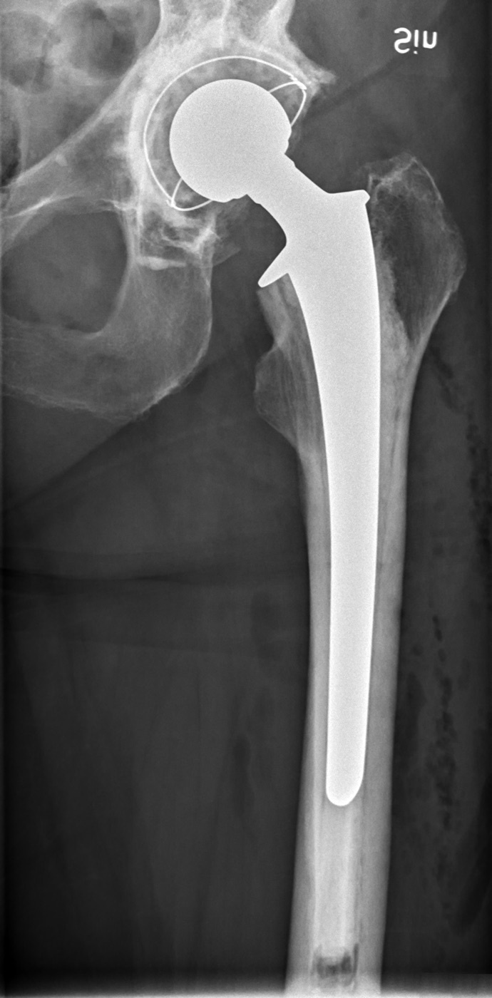
Figure 8. AP radiograph of a cemented femoral stem (the cement mantle is the lucent layer between stem and bone). Source: Mikael Häggström, M.D., via Wikimedia Commons, CC0 1.0.
Figure 8. AP radiograph of a cemented femoral stem (the cement mantle is the lucent layer between stem and bone). Source: Mikael Häggström, M.D., via Wikimedia Commons, CC0 1.0.
Cementless fixation
Biological fixation occurs by bone ingrowth into a porous coating or ongrowth onto a grit-blasted/plasma-sprayed surface. It requires a biocompatible surface, an optimal pore size of ~100-400 µm, intimate bone contact, and, above all, initial mechanical stability.[25] Excessive micromotion prevents ingrowth and produces fibrous tissue instead (above roughly 150 µm for cups; an ingrown stem shows < 20 µm), and gaps wider than ~2 mm will not heal with bone.[26] Press-fit (under-reaming by 1-2 mm) provides initial stability through hoop stresses; a hydroxyapatite coating is osteoconductive but must overlie a porous/grit-blasted surface (it fails if it resorbs from a smooth implant).[27]
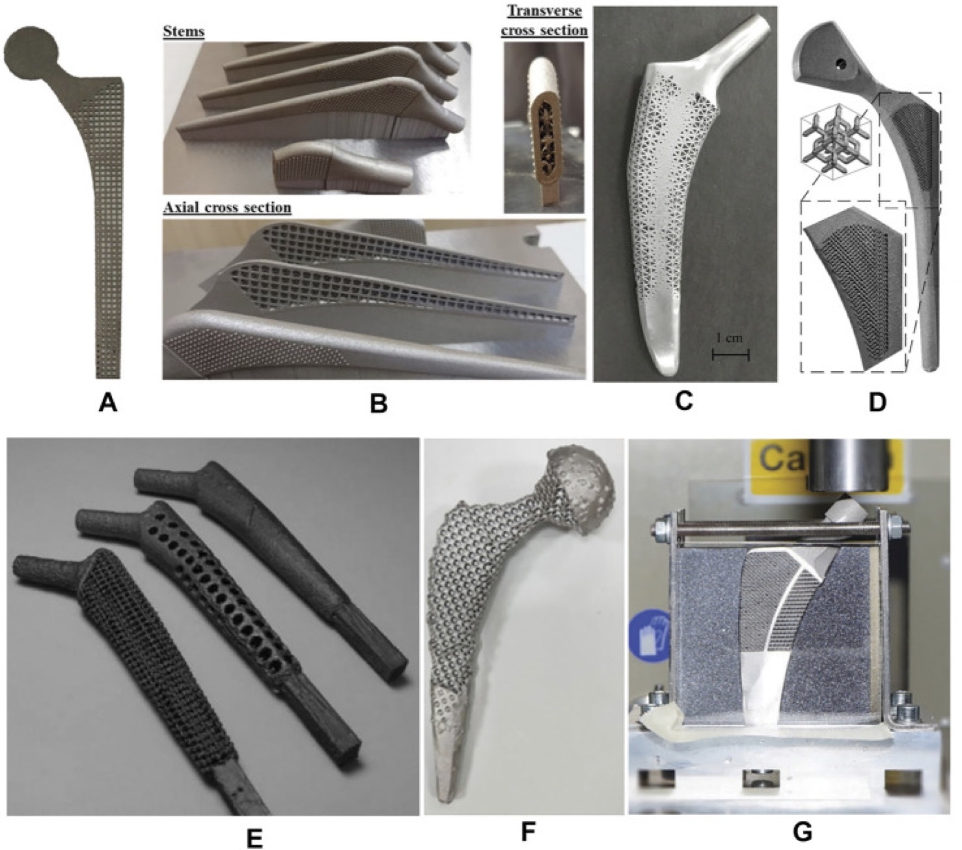
Figure 9. Cementless femoral stems with porous lattice (trabecular-metal) structures and cross-sections showing the internal porous architecture for bone ingrowth. From Liu et al. (2021), Front Bioeng Biotechnol 9:772539, PMC8637819, Fig. 3, CC BY 4.0.
Figure 9. Cementless femoral stems with porous lattice (trabecular-metal) structures and cross-sections showing the internal porous architecture for bone ingrowth. From Liu et al. (2021), Front Bioeng Biotechnol 9:772539, PMC8637819, Fig. 3, CC BY 4.0.
Stress shielding
Because a stiff metal stem unloads the surrounding bone, Wolff’s law drives proximal femoral bone resorption (stress shielding), on average a ~23% loss of femoral bone mineral, greatest proximally, described by the Gruen zones.[28] It is worse with stiffer (CoCr versus titanium) and more extensively coated stems, but is generally benign and not in itself an indication for revision.[29] Registry data generally favour cemented femoral fixation, while cementless tapered titanium stems achieve excellent survivorship with low thigh pain; the choice is individualised by age, bone quality (Dorr type) and canal shape.[30]
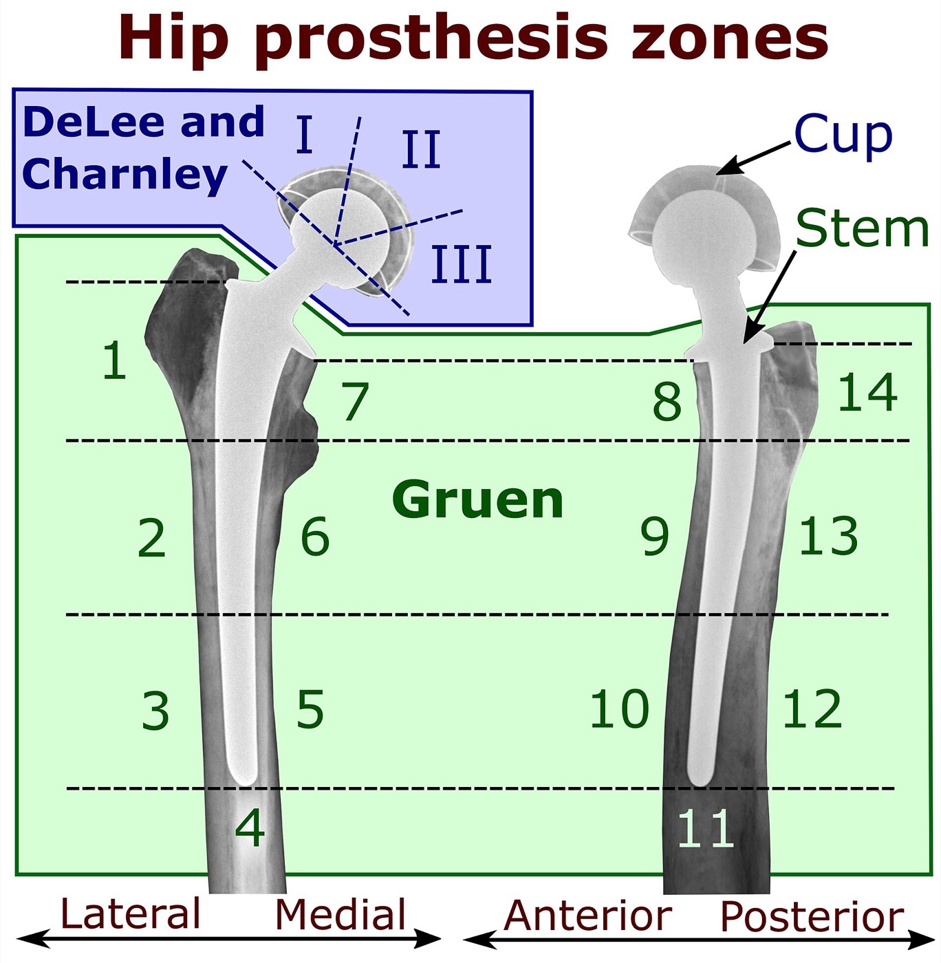
Figure 10. Periprosthetic zone systems: the Gruen zones (femoral component) and the DeLee-Charnley zones (acetabular component) used to describe radiolucencies, osteolysis and stress shielding. Source: Mikael Häggström, via Wikimedia Commons, CC0 1.0.
Figure 10. Periprosthetic zone systems: the Gruen zones (femoral component) and the DeLee-Charnley zones (acetabular component) used to describe radiolucencies, osteolysis and stress shielding. Source: Mikael Häggström, via Wikimedia Commons, CC0 1.0.
Part VI - Complications
Periprosthetic joint infection (PJI)
PJI complicates about 0.5-1% of hip replacements and is the commonest reason for implant removal.[31] Diagnosis combines history, screening ESR and CRP (normal values make infection very unlikely), and joint aspiration for synovial white-cell count, neutrophil differential and culture, supported by intra-operative frozen section (≥5 neutrophils per high-power field) and multiple cultures; the formal MSIS criteria codify these.[32] Infection is classified by timing (early postoperative, acute haematogenous, and chronic/late), and the biofilm explains the difficulty of eradication with the implant retained.[33] Treatment options, by indication:
- DAIR (debridement, antibiotics, implant retention): for acute infection with a well-fixed implant and short symptom duration; success falls sharply once symptoms exceed ~48 hours or with S. aureus.[34]
- One-stage exchange: a sensitive gram-positive organism, no sinus, antibiotic cement; more common in Europe.
- Two-stage exchange with an antibiotic spacer (articulating or static): the North American standard for chronic infection, ~90-95% success.[35]
- Suppression, resection (Girdlestone), arthrodesis, or amputation: salvage.
Prophylactic antibiotics within an hour of incision are the single most important preventive measure.[36]
Dislocation and instability
Instability is a leading indication for revision THA. Risk factors are patient-related (female sex, age, neuromuscular disease) and surgeon-related. The surgeon-related ones are chiefly component malposition (the Lewinnek “safe zone”: cup inclination 40 ± 10° and anteversion 15 ± 10°), the surgical approach (highest with an unrepaired posterior approach), head size (a larger head increases the jump distance and stability), and soft-tissue tension/offset.[37] Treatment ranges from closed reduction through component or modular-head revision and larger heads to dual-mobility and constrained liners for deficient abductors.[38]
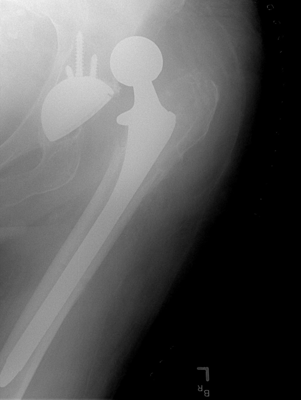
Figure 11. Dislocation of a total hip prosthesis: the femoral head lies outside the acetabular cup. Source: Bill Rhodes, via Wikimedia Commons, CC BY 2.0.
Figure 11. Dislocation of a total hip prosthesis: the femoral head lies outside the acetabular cup. Source: Bill Rhodes, via Wikimedia Commons, CC BY 2.0.
Periprosthetic fracture
Femoral fractures around a hip stem are graded by the Vancouver classification, which drives treatment: type A (trochanteric, AG/AL); type B around or just below the stem, subdivided into B1 (stem stable → fix with a plate/strut), B2 (stem loose, good bone → revise to a bypassing stem), and B3 (stem loose, poor bone → proximal femoral replacement or allograft-prosthetic composite); and type C well below the stem (fix independently per AO principles).[39] The cardinal error is treating a B2 as a B1, because fixing a fracture around a loose stem fails.
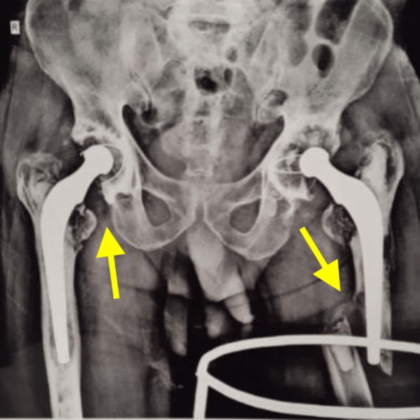
Figure 12. Periprosthetic femoral fracture (Vancouver B3) around the left stem of a bilateral total hip arthroplasty (arrows). From Suneja et al. (2024), Cureus 16(2):e53895, PMC10925070, Fig. 1, CC BY 4.0.
Figure 12. Periprosthetic femoral fracture (Vancouver B3) around the left stem of a bilateral total hip arthroplasty (arrows). From Suneja et al. (2024), Cureus 16(2):e53895, PMC10925070, Fig. 1, CC BY 4.0.
Other complications
These include venous thromboembolism (requiring chemical and mechanical thromboprophylaxis), nerve injury (the sciatic - particularly its peroneal division - in the hip; the peroneal nerve in valgus-knee correction), leg-length discrepancy, and heterotopic ossification (graded by the Brooker classification, prevented by indomethacin or radiation).[40]
Part VII - Total Knee Arthroplasty: Principles
The same biomaterials and wear principles apply to the knee, with important differences. Cemented fixation is the “gold standard” in TKA: the cemented knee is loaded primarily in compression, and comparative and registry data consistently show lower revision than cementless (Rand & Trousdale: 92% vs 61% at 10 years), so there is “no justification for cementless implants in any age” in this source’s view.[41]
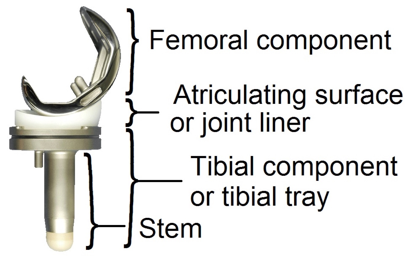
Figure 13. Components of a total knee replacement: femoral component, polyethylene insert (bearing), and tibial tray. Source: Graichen / Mikael Häggström, via Wikimedia Commons, CC BY 3.0.
Figure 13. Components of a total knee replacement: femoral component, polyethylene insert (bearing), and tibial tray. Source: Graichen / Mikael Häggström, via Wikimedia Commons, CC BY 3.0.
Design choices include cruciate-retaining (CR) versus posterior-stabilised (PS) articulations and fixed-versus mobile (rotating-platform) bearings; the polyethylene insert is the wear-critical component, and fatigue/delamination wear is more important in the knee than the hip (so highly cross-linked PE, with its lower toughness, is used more cautiously).[42] Outcome is governed by alignment principles: a tibial cut perpendicular to the mechanical axis, femoral rotation set to the transepicondylar axis or Whiteside’s line, and balanced flexion/extension gaps.[43]
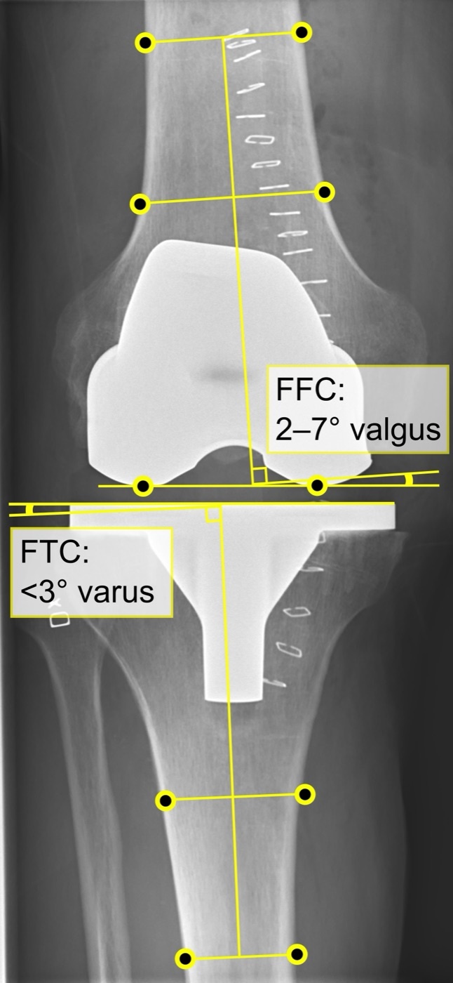
Figure 14. AP radiograph of a total knee replacement with post-operative alignment angles annotated. Source: Mikael Häggström, M.D., via Wikimedia Commons, CC0 1.0.
Figure 14. AP radiograph of a total knee replacement with post-operative alignment angles annotated. Source: Mikael Häggström, M.D., via Wikimedia Commons, CC0 1.0.
The infected TKA is managed, like the hip, by two-stage revision with a high-dose antibiotic articulating or static spacer.[44]
References
-
Berry, Surgery of the Hip, p. 120 (Table 6-3). The large mismatch between any metal and bone is the basis of stress shielding; titanium, at roughly half the stiffness of CoCr, is the metal closest to bone.
-
Berry pp. 115-127.
-
Berry pp. 123-124. Hip-joint loads reach 3-8.5× body weight.
-
Berry pp. 69, 915-919; Wright & Goodman, Implant Wear, pp. 213-230. Cross-linking also reduces fracture toughness, so dose is balanced against rim-fracture risk.
-
Berry pp. 130-142. Modern ceramic head fracture is on the order of 1-2 per 10,000; pure yttria-zirconia heads were recalled after in-vivo phase transformation.
-
Berry pp. 82-84 (Table 4-1).
-
Berry p. 85 (Eriksson & Albrektsson).
-
Berry pp. 85, 91; Charnley pp. 40-42.
-
Berry pp. 47-58.
-
Berry pp. 69, 140.
-
Charnley pp. 11-22. He also abandoned PTFE in 1961 for catastrophic wear and adopted high-molecular-weight polyethylene in 1962.
-
Berry pp. 63-66 (Stribeck).
-
Berry pp. 64-67; Implant Wear pp. 194-198.
-
Berry pp. 921-937; Implant Wear p. 170.
-
Implant Wear pp. 170-171; Berry p. 923.
-
Berry pp. 935-942.
-
Berry pp. 199-209, 921-931. Cup inclination >50° causes edge loading with sharply increased wear and ion levels; serum ion monitoring and cross-sectional MRI are recommended.
-
Berry pp. 1092, 885; the role of PE was proven by retrieval studies after cementless devices failed to abolish loosening.
-
Berry pp. 199-200; Implant Wear pp. 94-119 (Willert’s original mechanism).
-
Berry p. 1093.
-
Implant Wear p. 98 (Dowd); Berry p. 200. The pattern differs by fixation: linear at the cement-bone interface in cemented implants, expansile periprosthetic bone loss in cementless - which can stay osseointegrated despite massive lysis.
-
Berry pp. 838-841, 865.
-
Berry pp. 841-842, 870-871; the Barrack A-D grading is standard teaching, not named in the extract.
-
Berry pp. 865-867 (Shen). Taper-slip stems give the most consistent registry survivorship and permit cement-in-cement revision.
-
Berry pp. 847-849 (Bobyn; Albrektsson coined “osseointegration”).
-
Berry pp. 847, 851, 880, 886.
-
Berry pp. 849-851.
-
Berry pp. 876, 880, 895 (Gruen et al. 1979); “Wolff’s law” and the full seven-zone enumeration are standard teaching, expressed functionally in the extract.
-
Berry pp. 881, 894-895.
-
Berry pp. 873, 887-897.
-
Berry p. 1224.
-
Berry pp. 1226-1228; Insall & Scott p. 1809; the MSIS eponym is standard teaching, not named in the extract.
-
Berry pp. 1225, 1229.
-
Berry p. 1229; Insall & Scott p. 1810.
-
Berry pp. 1229-1231; Insall & Scott pp. 1812-1814.
-
Berry p. 1225.
-
Berry pp. 1235-1237.
-
Berry pp. 1238-1240.
-
Berry pp. 1251-1258 (Duncan & Masri). The intra-operative Vancouver scheme grades A/B/C × perforation/crack/displaced.
-
Berry pp. 654, 1237; Insall & Scott p. 1660; the Brooker grading is standard teaching, not defined in the extract.
-
Insall & Scott pp. 1648-1651.
-
Insall & Scott p. 1659; Implant Wear pp. 218-219.
-
Insall & Scott pp. 1653-1658.
-
Insall & Scott pp. 1807-1814.
-
Berry p. 120.
-
Berry pp. 85, 91.
-
Charnley pp. 11-22.
-
Berry pp. 921-942.
-
Berry pp. 199-200; Implant Wear p. 98.
-
Berry pp. 847-851.
-
Berry pp. 876-895.
-
Berry pp. 1226-1231.
-
Berry pp. 1235-1237.
-
Berry pp. 1251-1258.
-
Insall & Scott pp. 1648-1651.
-
Berry pp. 865-867.